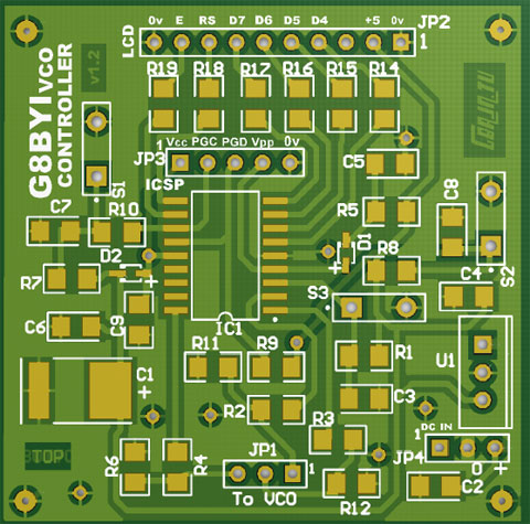
If you are using the original version 1.1 board QT110521 please use this circuit: BYI version1.1 Link JP3 pin1 to IC pin 14 & o/c C1 from +5v line during programming.
With the version 1.3 or 1.2 board the link is already fitted and C1 can remain in circuit. Remove the 5v power supply, set the programmer to ICSP (LVP off) mode, hook the programming plug to JP3 and program the chip. The programmer will supply the 5v line required as well as the 12v programming voltage to IC1 .
The BAT54 shottky diode can be either SOD323 or SOT23 package. I used the Farnell 1617723 version originally, but as it is only a DC block it is not a critical device.
If the programmer will not recognise your IC try unplugging any loads such as LCD before programming. Ensure the programmer is set to ICSP mode.
Download Hex code: VCOPLL5.HEX![]()
This is a text file. Copy it (cut and paste) to Notepad then save as VCOPLL5.hex
to your C: drive or preferred folder. Use your programmer to program PIC16F628A.


Instead of adding a PIC control board, John has reprogrammed the Ultam board PIC to allow a two frequency option.
Yet Another Way to Change Ultram VCO Frequencies
by John O'Loughlin
I have developed a PIC program for the Ultram VCO. It can be used to program any two frequencies the user requires in either the 23cm or the 70cm VCO band. It is not necessary to recompile from source code to set the frequencies. To program a custom frequency the parameters are first determined by using software from Analog Devices. Then they are inserted into easy to find locations in the HEX file with the PIC programmer software. Like the G8BYI program, the frequency is selected by changing the state of pin 5 of the PIC. The abilities required for this project are the soldering skills needed to change an 8 pin SOIC PIC and the ability to use PIC programming software.
History
Two versions of the Ultram VCO module are sold on the BATC website for use as the DigiLite local oscillator. https://www.batc.org.uk/shop/hardware-and-kits Their fixed frequencies are 1249 MHz (23cm) and 437 MHz (70cm). The major components of the VCO are a PIC12F629 microcontroller and an Analog Devices AFD4360 Integrated Synthesizer and VCO. The PIC sends data to the ADF4360 at power up to set the frequency and several other operating parameters.
As some users may want to operate on other frequencies the BATC also offers a PCB for a DIY VCO control module for the 23 cm version. The PIC microcontroller is removed from the Ultram VCO and the set-up data are sent from the VCO control module. While this module does provide a way to easily change the frequency over a wide range it cost about as much as the VCO and takes a skilled hobbyist several hours to assemble and is only programmed for 23cm.
Alternative methods are offered on G8AJN’s website. http://www.g8ajn.tv/dlindex.html They are the preset tuning board, the full tuning board (instructions for the BATC board), and the F1CJN tuning board. Also there is the G8BYI code for reprogramming the PIC on the 70 cm Ultram VCO to provide two selectable frequencies, 436 and 437 MHz.
DigiLite Local Oscillator Frequency Change PIC Program
The 23cm Ultram uses an ADF4360-5. It can be programmed for 1200 to 1400 MHz. The 70cm Ultram uses an ADF4360-7. It can be programmed for 350 to 1800 MHz. However, unlike the ADF4360-5, the range of its internal VCO is set by external components. Pins 9 and 10 of the ADF4360-7 each have an inductor and a resistor in parallel to ground. Both are size 603. The range of the VCO as it comes from the vendor is approximately 430 to 530 MHz. To obtain 427 MHZ (USA) the two inductors and two resistors need to be changed to 22nH and 470R. The inductor value for other ranges can be determined from the chart in the datasheet. I have not experimented to see if that version of the Ultram’s output amplifier can operate outside the 70cm band.
Links
ADF4360-5: Integrated Synthesizer and VCO Data Sheet (Rev B, 11/2012)
ADF4360-7: Integrated Synthesizer and VCO Data Sheet (Rev C, 11/2012)
Evaluation Board Software This software from Analog Devices is intended to be used with an evaluation board but it can be used to determine the set-up parameters. First the details for a known frequency setup are entered, then simply changing the frequency will give the new parameters.
Procedure for determining ADF4360 Setup Parameters
AFD4360-7 The data are three 24 bit words, shown in hexadecimal notation here.
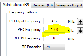
Values for Freq = 437 MHz
PFD Freq = 1000 ( this entry is decimal)
Control = 6E124
R counter = 29
N counter = 3616
Start the ADF4360 program, choose ADF4360-7 and hit the “OK” button.
The “Main Features (F2)” tab will be selected.
Enter 1000 in the “PFD Frequency” field
Select the “”Register (F3)” tab and change the 3 latch register fields. Hit the “Update Latches …” button.

Return to the “Main Features (F2)” tab and enter the new frequency. The latch info will update when you select a different field. In this example the PFD Frequency is 1000 kHz so the new frequency must be a multiple of 1 MHz. Other PFD frequencies can be used, read the datasheet for information. Record the latch data for modifying the PIC HEX file. The values in the image below are for 433 MHz.

To determine parameters for 23cm use the same procedure, select the ADF4360-5 at the start and use the values below.
The 100 KHz PDF freq allows the selected frequency to be multiples of 0.1 MHz.
Parameters for 23cm:
AFD4360-5 - 23 cm
Values for Freq = 1249 MHz
PFD Freq = 100 ( this entry is decimal)
Control = 8FE924
R counter = 300191
N counter = 1862A
Programming and changing the PIC
Remove the PIC from the Ultram and save it in case you’re not successful in programming the replacement ( PIC12F629-I ).
www.chipquik.com This product makes it easy to remove surface mounted devices. It’s not the only way to remove the PIC but it does make it less likely you’ll damage the board or the PIC. An 8 pin SOIC Adapter for PIC programming can be made from a test clip. Wire as required for your programmer. The PIC is programmed in the clip and then soldered onto the Ultram board.


ROM locations for Ultram VCO frequencies in PIC file = DL LO FREQ.HEX
The values here are for 23cm, in this case the R counter = 300191.
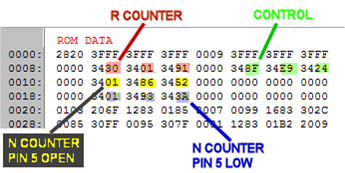
Change the ROM values to the parameters determined with the ADF4360 program and program a PIC12F629. Only the N counter values are different for two frequencies in the same band. Solder it onto the Ultram VCO board and use pin 5 to select the desired frequency.
Extra for Arduino Users:
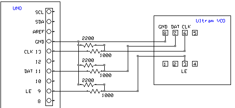
Here is a program for sending the setup parameters from an Arduino UNO. It’s handy if you want to experiment with a lot of different settings of the ADF4360.
Ultram_SFT.ino
 n
n
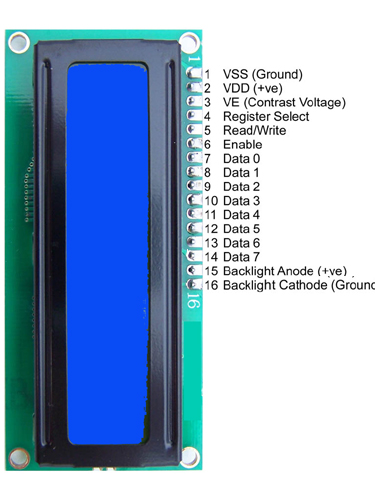
Connections to the standard Hitachi LCD display 2x16 or 2x20
Pin3 can go to the slider of a 10k pot between +5 and GND but with 220 ohm minimum from pin 3 to +5 or slider or you may damage the display chip.
Other similar displays appear to use the same numbering but contacts may be vertically aligned.
Tie pin 5 to GND. the unused data pins e.g. 7,8,9,10 can be grounded but not important to do so.