
The original oscillator is a single frequency device, but by replacing the on-board 8 pin PIC with this simple unit you can select one of five preset channels using a single press button switch.
The on-board regulator allows it to run from 8 to18 volts dc.
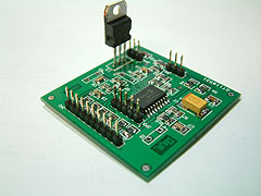
The components list should show PIC as 16F628A . A mirror image pdf is here.On the prototype board shown I have fitted the leds and switch to the board, but of course they would normally be mounted on the front plate of a box. The wiring is non critical and could even be made on Vero if preferred. The 5 way socket (not fitted in picture) is optional, ribbon cable can be soldered direct. Richard has also produced a fully tuneable version of this board, developed in parallel to the F1CJN board shown on the next page.
His version is fully smd with an on-board PIC and it is described in detail in CQTV237. Now published it appears on sub-page 3 for completeness and for updates and software download.
A commercially manufactured pcb is now available (BATC Shop) and it will useable with either the simple or the full circuit. It has been suggested that the values of the 10K pull-down resistors R10,R12,R13 should be lowered to 910 ohms to avoid overdriving the ADF vco chip inputs. Whilst no reports have been received of any problems it would be a wise precaution.The same G8BYI controller board can be used with either the Simple Controller or the Full Function Controller.
I
![]()
![]() OTHER ITEMS
2 / 7
OTHER ITEMS
2 / 7
A very useful add-on for the Utram Tech local oscillator used with the DigiLite board. Expands function of Ultram VCO board
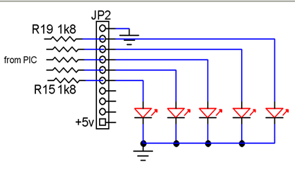
to 5 Preset channels: 1244,1248,1249,1262,1280Mhz .
Others may be programmed instead.
In this diagram the first diode (usually top one) is fed from R15
R14 can be used to run out PIC Pin 6 to the step button if desired..

TIP: If you find nothing working after programming the PIC chip it may well be that the programmer 'fuses' are not set correctly.
On the K150 you should use the IRCCLK option, other programmers may call it something like...intrc_osc_noclkout.
I have a small stock of the G8BYI controller board bare pcbs here at G8AJN. Details on the STORE page (same pcb as the full tuning version but uses different software)
![]()
You can use the BATC VCO controller board (either version) even if you only want to have the 5 LED (simple) version. You will need to use this different HEX FILE . Use the circuit as per the Full tuning version board, but replace the 0 ohm resistors with five 1k8 (or higher to suit your LEDs) limiter resistors to drive the LEDs. R14 changes to 10k to supply dc and permit the Stepper switch to ground Pin6 of the IC. A link from R14 (pin 6 end) to the spare pin 3 of PL2 could be used to connect to +5 or R14 might be a zero ohms link and the 10K and switch could be mounted off-board.
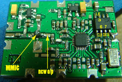

Here is a photo of the v1.3 board being used for the basic 5 LED version software.
As you can see R14 is a 0R link to the yellow ribbon wire. I have also sneaked a decoupling cap from IC1 pin 6 (10nF) to ground to minimise contact bounce.
![]()