Using the DigiLite on 70 cm by John O'Loughlin and Gary Grivna K0GX
Here are the items we addressed in building a 70cm version of the DigiLite. The AD8346 modulator was replaced with an AD8345.
N.B. Because the AD8345 has a much higher RF output it has an exposed pad on the bottom that improves heat dissipation when it is soldered to the circuit board. Since the DigiLite board has no provision for this, the junction-to-air thermal impedance is three times higher. 70cm boards should have good air flow and improper adjustment could increase the RF output causing more heat.
* (The latest version board, v5.9 has now got a ground plane to suit the AD8345 and should not need any futher cooling.G8AJN)
LO input
AD8345 typical input is -2dbm. The Ultram output measured 10dbm, so with the 12db attenuator in the Digilite it’s a match!
RF output
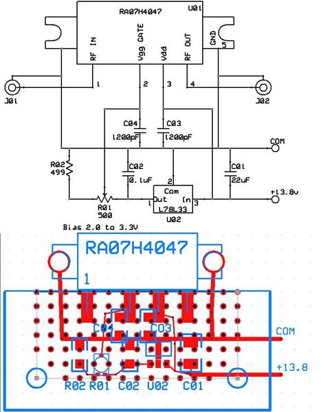
AD8345 typical output is about 0dbm. The MAR6 P1db is so close to that one may as well remove it and its input attenuator and run the AD8345 straight out. We replaced the MAR6 with a Sirenza SGA-5589. We increased its input attenuator loss by changing the resistors, to 127 ohms shunt, 46 ohms series setting up the SGA-5589 for 15dbm out. The more standard values of 120 and 47 ohms would work well too. Improvement of the SGA-5589 performance could probably be made by someone willing to put in the effort to optimize the surrounding part values. The new output actually measured 14.8 dbm, enough to drive an RA60H4047 to 40 watts. PLEASE NOTE: Due to the simple filtering used on the DigiLite it is ESSENTIAL that proper filtering is used on the transmitted signal to avoid exceeding bandwidth limits.
PLEASE NOTE:
Due to the simple filtering used on the DigiLite it is ESSENTIAL that proper filtering is used on the transmitted 70cm signal to avoid exceeding bandwidth limits.
I-Q drive
The AD8345 drive and bias voltages are much lower. Lowering the signal with the pots only would result in an unbalance of the differential input to the AD8345. We changed resistors in the voltage dividers to the AD8345 inputs, R15, R18, R22, R25 to 422 ohms. The voltage at the AD828 outputs will be the same as with the AD8346 therefore the setup procedure will be the same as the 23cm version.
Misc
Several RF coupling caps were increased too. We have also used the SGA5589 on the 23cm DigiLite to get higher output and for the preamp before the RA18H1213 power amp. We had a couple failures we suspect were due to operating without a load on the SGA5589.
Here are the new values of the parts we changed:
R15, R18, R22, R25 = 422 Ohms
R34 = 47 Ohms
R36, R37 = 120 Ohms
C30, C31, C28, C29 = 270pF
IC4 = AD8345
U5 = SGA-5589Z (e.g.RFBay on Ebay approx £7.50 for 5)
R41= remove
R26=68 Ohms
Setup Procedures:
When K0GX and I were researching our first 23 cm DigiLite the concept of setting it up by observing the satellite receiver quality meter sounded a little hit and miss. However we were able to find an L band spectrum analyzer at a very good price and incorporated it into our setup method.
The AD8346 datasheet specifies that the signals at the I and Q inputs should have an AC swing from 0.7V to1.4V. Examining the DigiLite modulator circuit shows the signals at the AD828 op amp outputs will be twice that, 1.4V to 3.4V. By using an oscilloscope that signal waveform can be easily achieved by adjusting the BIAS and LEVEL pots.
Further circuit analysis determined the main effect of the BIAS pots is controlling the balance of the differential inputs to the AD8346. That controls the amount of carrier (LO) leaking through the balanced modulators to the RF output. The LO leakage can be eliminated by adjusting the BIAS pots while observing the spectrum analyzer.
Setting up with these methods resulted in 99% quality, the highest the receiver displays.
Dave G8AJN assured me in email conversations that it really is possible to get a usable signal using just the satellite receiver 'quality' meter, so I starting wondering how that could be.
We setup the DigiLite on the bench and observed the results of adjusting the pots on an oscilloscope, a spectrum analyzer, a satellite receiver and a digital voltmeter.
The voltage affecting the differential balance of the I-Q drives can be measured on the LEVEL pot from the wiper to the TLE2426 end. With the LO nulled out, the voltage measured about 8mV with the DVM. When the BIAS was adjusted for 0V the LO leakage was about -50db from the signal. The bias was then adjusted until the quality meter reading decreased to 90%. At that point the voltage was 150mV and the LO leakage was -15db under the signal. This demonstrates that the DigiLite tolerates large offsets and that the BIAS pots can be set for a very acceptable LO leakage with just a DVM.
We also checked the DigiLite’s tolerance of LEVEL pot misadjustment. The nominal peak to peak level is 2V. The Q LEVEL was adjusted from 2.5 Vpp to 1.5 Vpp with no change in the 99% quality reading. The quality fell off the cliff to 0% at about 1.3 Vpp. The same results were seen when adjusting the I LEVEL. Again this demonstrates that the DigiLite tolerates large offsets.
These tests show setting up the Digilite with only a DVM gives results very close to using an oscilloscope and spectrum analyzer.
The I and Q signals are generated by logic outputs switching from common to 5V, therefore the level of the signals leaving the Nyquist filter will be the same, within a few percent, on all units. Because their input is consistent the LEVEL pots could be adjusted to a standard ratio or even replaced by fixed resistors, probably 33 ohms and 68 ohms. A little more testing would be needed to verify those values. Setting the pots by measuring the resistance may not be accurate because of the influence of the surrounding components. I have worked out a way to set the LEVEL pots with the DVM by measuring voltages.If you would like a detailed description of the bias arrangements click here.
How and why the DVM setup procedure works.
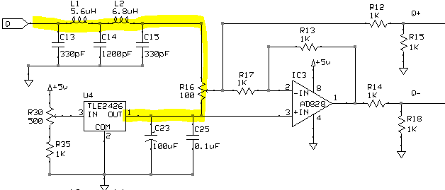
I’ll refer to the Q signal in this discussion, the I signal operation is the same. The bias at Q+ and Q- should be 1.2 volts for an AD8346. The voltage at the top of R12 and R14 should be double that, 2.4V. The 70cm version has different divider resistors to accommodate the AD8345’s lower bias voltage so the same voltage is required at the top of its dividers. The center voltage of the signal at Q, the input to the Nyquist filter, is halfway between the power rails, about 2.5V. If the BIAS pot R30 is adjusted so U4 puts out the same voltage as the Nyquist filter your DigiLite will be close to proper bias adjustment, but there are still a few other factors to be considered.
When you raise or lower the BIAS, the difference between the U4 voltage and the filter’s center voltage will cause current in the path highlighted in yellow. The voltage drop across the LEVEL pot R16, from the wiper to the C25 end, will cause the bias voltage at Q- to be different than at Q+. Thus by adjusting the U4 voltage a little bit higher or lower you can change the balance of the differential input to the AD8345 or AD8346 and control the LO leakage. Q- and Q+ drive a balanced modulator. R12 draws current to ground causing the voltage at the wiper of the BIAS pot to be a bit lower than the filter output. As a result, the bias at the dividers is about 2.4V when the BIAS pot is properly set.
Note: If you were to install an AD8345 without changing the divider resistors you would either operate at too high a bias or the balance would be way off center.
After the LO leakage was nulled out using a spectrum analyzer the voltage from the wiper of the LEVEL pot R16 to the C25 end was found to be < 10 mV. Setting that voltage down to zero caused only a slight amount of LO leakage. Also the Digilite still puts out 90% quality with 150 mV of offset. This explains why setting the bias to zero with the DVM will reduce the LO to an acceptable level. Setting the test mode to IN PHASE sends a 50-50 square wave into the filters for consistent center voltage.
The peak to peak voltage of the I and Q signals were first set to the proper levels with an oscilloscope. The position of the wiper was then calculated by measuring the Vpp in and out of the LEVEL pot. It was found to be 67% or 68% on both a 70cm and a 23cm DigiLite. The DVM level setting procedure begins by setting the BIAS pot far enough off center to put 200 mV across the LEVEL pot. The voltage from the wiper to the end is set to 100 mV, the voltage measured on the properly set units. This may seem to be different than the 68% ratio just mentioned but the current through R12 explains the apparent error. This technique will set the level well within the range that will give good quality.
John O'Loughlin
Modified circuit diagram for 70cms here
Digital Voltmeter Set-up Procedure:
Using the DigiLite config program, set the Test Mode to IN PHASE.
*Connect the negative lead of DVM to the TLE2426 end of the LEVEL pot (B2) and the positive lead to the other end.
Adjust the BIAS pot for a reading of 200 mV.
* Measure the voltage from the LEVEL pot wiper to the end connected to the TLE2426.
Adjust the LEVEL pot for 100 mV. (sets the drive level)
Measure the voltage from the LEVEL pot wiper to the end connected to the TLE2426.
Adjust the BIAS pot for 0 mV. (sets the bias/balance)
Repeat for the other channel. (* If LEVEL pots are replaced with resistors the first 2 steps* will not be required.)

Using an oscilloscope is a more accurate method of setting the level if you happen to have access to one.
Connect the oscilloscope to IC3 pin 7. Adjust LEVEL pot R23 and BIAS pot R29 for a 2 volt peak to peak
sine wave signal swinging from 1.4 VDC to 3.4 VDC. Connect the oscilloscope to IC3 pin1.
Adjust LEVEL pot R16 and BIAS pot R30 for the same waveform. Then perform the last step in the DVM procedure to zero the bias.
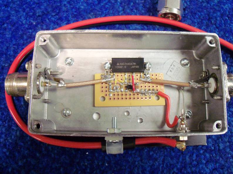
The DigiLite Team would like to thank John and Gary for their interest and great care with which they have approached this project. The SGA chip (and others) do not like working into an open circuit, so please ensure a 50 ohm load is always present. As this work was done in the U.S. the Nyquist filter components used on 70cm were for 4Ms/s. This is not an option for the UK of course, see values below. Note the settings of the presets in the zoomed photo.