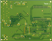

The serial data that is generated by the DigiLite Transmit program is taken from the USB2 socket on your pc and is connected via the Mini-USB socket on the FT2232H sub-panel at the edge of the serialiser board.
If a card reader is used later most of the connections required also are available at this header (JP1).
The dsPIC333 is an interesting device. It is designed specifically for handling digital data streams at up to 40MIPS with lots of useful timing features. Refer to the manufacturers data sheet for more information.
The I and Q signals go to the 74AC574 latching flip-flops. The output of these eight latches are paralled to give four outputs ,I and Q and I* and Q* ensure accurate timing of I and Q phase components. Closely matched values of components here is important to ensure balance is maintained. Then the signals pass to the Nyquist filters.
A critical part of the modulator, the Nyquist filters, trim the skirts of the signal by filtering unwanted harmonics and reduce inter-symbol interference. Axial leaded inductors have been used here to ensure a high Q value, the smd versions tend to be lower Q
Radial inductors are proving difficult to source so the inductor pads have been changed to SMD. From version 5.9 the inductors have been replaced by the SMD 0805/1206 versions. If possible use 5% or better tolerance inductors and capacitors in the filter circuit, do not mix types on I and Q channels, they need to be as near identical as possible.
U3 and U4 are half dc rail regulators giving an accurate 1/2 voltage for the bias pots.This voltage is applied to the bottom end of the I and Q level pots giving the required dc offset for the inputs to modulator chip AD8346. The modulator IC also requires a carrier of around -8dBm at the desired output frequency. This must be a good quality (low phase noise etc) signal. If you have less drive you may remove the attenuation at the input with resistors R27,R28,R38 currently set at about 12dB. The input can be capacitively coupled without the balun (with the other input AC grounded with 50R (100R+100R) but it is less efficient and can give poorer output waveforms.The -10dBm modulated output is AC coupled through C24 into a MMIC rf amplifier/buffer stage.
Several further amplifying stages will be needed to get it to levels required for driving the PA stages, an interdigital filter is an important essential.