THE SERIALISER BOARD
Before the DigiLite board appeared the encoders were built as two separate items.
If you wish to make your own boards here is the info.
....
The DigiLite Serialiser is the device that receives the transport stream data from a PC USB port and converts it into two bit streams (I and Q) for the modulator.
.click images to download a pdf version
 The G8AJN IQ modulator board pdf download
(Note: whilst the circuit is basically the same as the G0UHY one,
the component numbers and layout are different).There is only one tricky part to fit, the mod chip AD8346 has very narrow spacing on its pins, the best way to fit it is to tin the ic pins on the board first then use solderwick to remove most of the solder, then align the end pin and solder it (using fine gauge solder) and carefully work round the pins. Use the solderwick to clear any accidentally linked pins.You will need :- a small tipped soldering iron, a magnifying bench lamp, 22swg or smaller solder, solderwick, a large mug of coffee.
If you dont have a Spectrum Analyser available, use a sat receiver and set the info screen to show signal quality and strength. Aim for highest quality, careful trimming of pots should get you to over 90%. The LO must be fully screened, otherwise it will radiate and mess up any readings you try to make.The level of the Local Osc input is important, the input is bottom left of picture here and there is a pi attenuator which you can change to suit the drive your l.o. generates.You are looking for 6 to 10dBm input to the balun, any more will require attenuation. Calculator here.
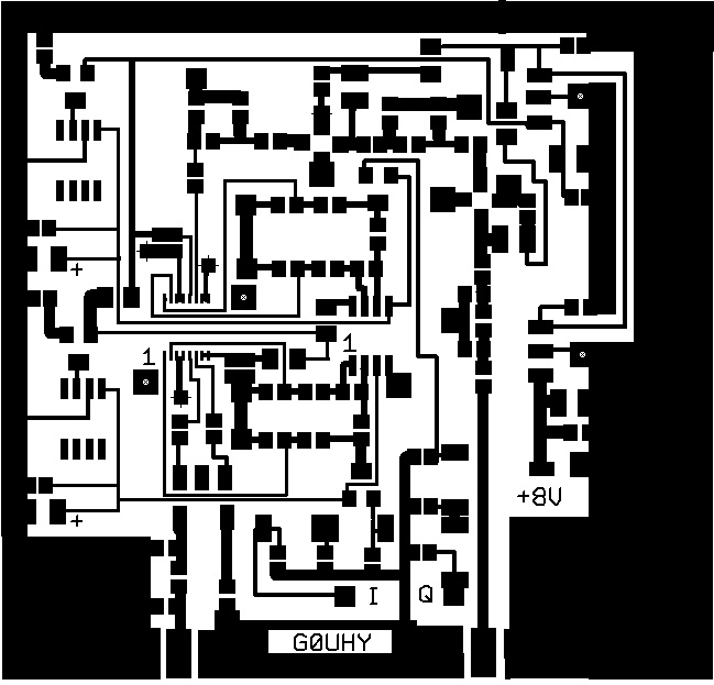
Original G0UHY IQ Modulator board
G0UHY mod board pcb design download here:
(Eagle CAD format) Circuit diagram. Not available.Use overlay in CAD file.
The circuit is the same as in the G8AJN version but component numbering is different. Components parts list.
Status indications and commands are transferred to / from the PC on a second channel
.LED INDICATOR:
Steady on / off at 1Hz Normal operation – data is being received.
2 flashes every 2 seconds Waiting for data from the USB port.
3 flashes every 2 seconds An invalid symbol rate or FEC has been received.
Operation continues at the previous settings.
6 flashes every 2 seconds Test mode active
Do not insert the 28 pin dsPIC333 chip until after the USB module has been configured.
SD card operation is not available in serialiser software versions starting with 1.
Do not insert an SD card in this case, or the serialiser may not operate correctly.
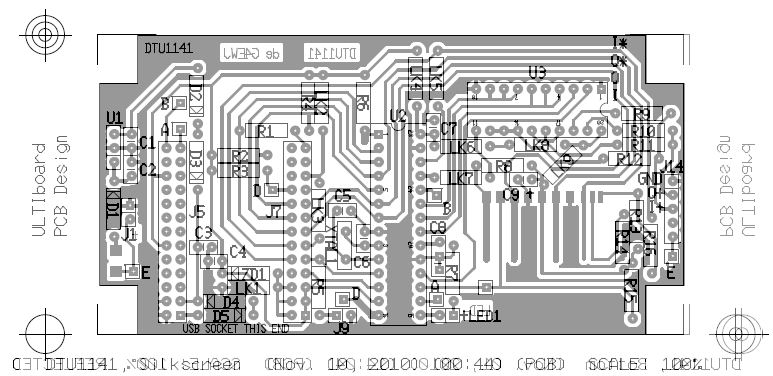
There are a lot of holes to be drilled as you can see from the overlay .The 20 pin 74AC574 latch chip could be soldered directly into the board if preferred.The IQ outputs are on the left of this picture and go to the modulator board.
Links on this build (by G4KLB) have been fitted underneath the board to improve visibility for the picture, but can be fitted on either side .The FT module is available ready programmed from BATC
PARTS LIST FOR THE SERIALISER
Notes:
There is no dc feed for the panel as it takes its supply from the USB feed of the PC. When you connect the usb lead the l.e.d. on the serialiser will blink. Now you need to check the COM port settings are correct using Control Panel settings and ensuring that they are entered into DigiLite CONFIG settings. More details in software section. The 3.3v zener is no longer required and can be ignored .
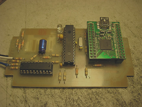
The USB2 interface card plugs into two dual 13 pin headers, allowing access to the components mounted on the main board between the headers. The diodes D4 D5 are Schottky wire ended diodes, the other diode is an LED.
This is used to indicate when a valid transport stream is being received by the PIC333 chip. The usb board requires programming (see software downloads on Software page). The usb lead used to connect to the PC is a USB plug to a USB mini type plug.(Seen here on top of the sub-panel). The gap behind the blue electrolytic cap in the picture is where the optional SD card reader sits underneath.This is for generating a test card or slides where the pc is unavailable,eg mobile.The software for the card reader is not included in the current software version.
Board size 55mm x107mm