

DC REGULATORS: When purchasing the 5v regulator for the DigiLite please note that some of the cheaper versions require minimum 10v input and often handle only 500mA maximum current. The original design has the 5v regulator using the output of the 8v regulator rather than the 12v supply to spread the heat requirements of the two regulators. Please use the TS7805CZ or equivalent (CPC:SC10582) ( RS:398-697) (Farnell:7173989). The 8v regulator handles the same current as the 5v regulator plus the L.O. board of course so ensure that the type you use is man enough. The MC7808CTG is preferred.(RS:516-4806).Original Part Numbers listed for the filter inductors and some of the tantalum capacitors were incorrect, use new parts list. Increased decoupling: the value of C22,C25,C12 increased to 0.1uF and C4 to 0.47u. Can be piggybacked onto original components if preferred. Resistors R31, R35 should be increased to 1k from 100R to improve bias pot range . If your regulators are running hot, try some extra decoupling on their input and output pins.( 0.47uF instead of 0.1uF). This seems to be a problem on some brands of regulators or external power units only. The original devices used were TS7805CZ / MC7808CTG and did not require additional decoupling.
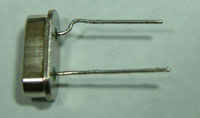
DigiLite version 5.8 only:A couple of points arising on the layout, the crystal leg spacing is slightly wider than the regular 5mm spacing. One leg of the xtal will need a 1mm knee in it to fit flush with the pcb. Don't force the xtal without bending the leg to fit first.
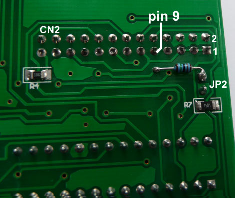
An error has crept in on the top side print. The 1K2 resistor (R42) has lost its solder pads. However, R42(and JP2) is only required if the SD card add-on is being used. A wire-ended 1/4 watt can be connected from the back of the socket JP2 to pin 9 of the CN2 socket. The adjacent via can be used if preferred. See photo of bottom tracking.
These points have been corrected on the later pcbs.
HELP! MY DIGILITE DOES NOT WORK!
The best approach to fault-finding is to check the separate areas of the DigiLite and follow the signal path in each area.
THE DATA :
Is the WinTv recording onto your hard drive ok? Find the file you have recorded and click on it to run it as a mpeg2 video file. It should run on your pc with your installed viewer program eg Windows Media Player.
THE USB INTERFACE :
Is the LED on the DigiLite(DL) winking once a second? If not, investigate the USB com port on your Windows/
Control Panel/Hardware Devices to ensure that the USB is being recognised by the PC.Check your settings on the DL Config program and ensure the DL Transmit program is finding the mpeg file on your drive.
THE BOARD:
Assuming all the above check out ok and the led is good, you may have a problem with your construction. There are lots of quite close connections on the DL board so a good magnifying bench lamp is essential. Check across the board for poorly soldered components. SMD components can be 'askew' and that will allow short circuits to nearby parts. Wrong values are another possibility.Ensure the SMD chips are seated flat to the pcb.You may have applied solder to the pin but the pin is not actually seated onto the pcb track beneath it.
VOLTAGES:
The board draws about 140mA at 12v in. Check the 3v,5v and 8v lines are ok. The pots
R29/R30 (I & Q Bias) should have about 4v on their sliders, R16/R23 (I & Q Level) should have 2.1v on sliders.
The modulator chip IC4 should have 3.5 to 4 v on its out pin 11. The output leg of the MMIC should have about 4v on it.
Using a 'scope to see the waveforms from the serialiser into the modulator section is difficult as the data can be hard to lock onto and appears 'jumbled &distorted' but it should be very similar on the I and Q lines.
One of the most common causes of no digital output is the level of the local oscillator in on JP2 being too high . If you are using the Ultram board take the drive from before the MMIC and remove the DL input attenuator resistors R28 and R38 and fitting a link, 0R smd, as R27. This should get you a local oscillator input of the correct level for the mod chip.
I have been involved in getting a couple of boards running for locals.
In all cases when the dc levels appear to be correct and wiring/soldering errors have been eliminated, the fault is often too much local oscillator signal. Keep wires short, keep oscillator well grounded . Use the 8v supply on the DigiLite board to run the Ultram board or fit its own regulator if preferred.
If you are not using the Ultram VCO board make sure that the phase noise figure is good enough for digital modulation.
If you are using the Ultram, remove the MMIC and link past it to take the local oscillator out from the VCO board.
(No reason to amplify the drive level with a MMIC only to attenuate it all away again at the input to the DigiLite board!)
There is sufficient signal from the VCO chip output to operate the modulator chip via the balun but you may need the three attenuator resistors on the input of DigiLite board removed and R27 (82ohm) replaced with a 0 ohm resistor to couple the local oscillator signal to the balun.
Hook the output of the DigiLite board to the aerial socket of the satellite receiver (watch the dc line to the lnb!) directly or lose coupled twisted wires and aim to get at least 60% signal level. Signals bouncing around a room will distort or even cancel out and cause great difficulties in setting up .
If you wish, you might try in-line attenuators on the local oscillator feed.
If after checking for solder bridges and unconnected pads there is still no output, check capacitor values (not easy as they never bother to mark them) as we have come across two instances of wrongly supplied values (100 times too large!). These were on the nyquist filters, had they been decoupling it would never have shown up, so start with the critical components.
Here is my preferred method of initial setup:
Set all four pots to mid-way.
Gently and slowly edge one of the 'level' pots watching the satellite box info display. Move the two pots in equal steps so that they are set to roughly equal settings.
It takes a moment or two for the receiver 'Quality' reading to kick in. Once it has, move to the other pots and aim to raise the level of the quality reading until the level drops back down again.
If there is no 'Quality' reading leave the 'level' pots at centre travel and adjust the two bias pots a small nudge clockwise and repeat the settings described above of the level pots.
The dc readings on the level pots are also affected by the dc coming out of the 74AC574 IC1. Check the 3v line is within tolerance. Check voltages on the output pins of IC1. Always read IC voltages on the IC pins not on nearby components. Patience gets results. Visit the BATC Forum and ask for specific help there, please check the above first before asking for help.
Don't get despondent, every board has been made to work thus far, we are happy to ensure that yours doesn't spoil the record!
Correcting errors is all part of the learning process.
Good luck,
Dave G8AJN
SUB-PAGES