

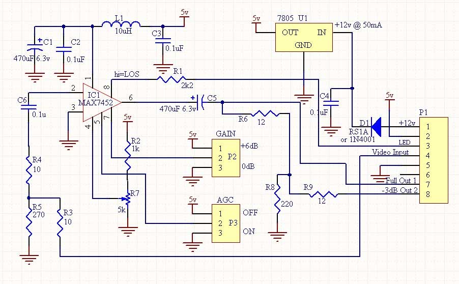
VIDEO BLACK LEVEL CLAMP AND AGC
(Link AGC ON / GAIN 0dB)
Pin 1 : 5v
Pin 2,4,6 : 1.5v(varies with R7)
Pin 3,5,7 : 0v
Pin 8 : 0.14v
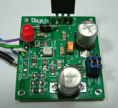
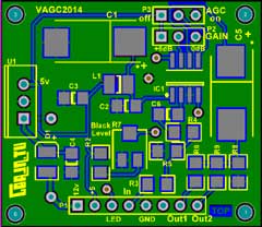
Double sided board size: 40mm x 35mm (approx 1.5" x 1.75").
DC input is 10v-12v @40mA.
There is no real setup to make, the preset R7 should be set to midway initially (about 1.8 v on the slider),
with the links set to AGC ON, GAIN 0dB
INITIAL SETTINGS:
I recommend simply fitting a 75 ohm resistor in series with the input
video, e.g. R3 =75R, R4=0R and R5 O/C.
Use a 47uF for C5 initially
and connect a monitor straight to full output (pin 7 of J1). You may find that this is all you need, if so other attenuator components can be left off. Set preset R7 to mid-way. C5 is optional, if being used in a 'd.c. safe' environment it should be replaced by a 75 ohm resistor, there will be about 1.5v DC sitting on it, but there would be better clamping than using a capacitor. Due to unique internal circuitry a lower value capacitor than usual will generally be sufficient,so I suggest trying a 47uF initially but go up to 100uF if there is poor lf response..
R3&R4 / R5 |
Preferred |
Values | |
| 75ohm | Actual |
E12 |
E24 |
| 1dB | 1304 / 8.6 | 1200 / 8.2 | 1300 / 9.1 |
| 2dB | 654 / 17.4 | 680 / 18 | 680 / 18 |
| 3dB | 438 / 26.4 | 470 / 27 | 430 / 27 |
| 4dB | 331.4 / 35.7 | 330 / 33 | 330 / 36 |
| 5dB | 267 / 45.5 | 270 / 47 | 270 / 47 |
| 6dB | 225 / 56 | 220 / 56 | 220 / 56 |
| 8dB | 174.2 / 79.2 | 180 / 82 | 180 / 82 |
| 10dB | 144.3 / 106.2 | 150 / 100 | 150 / 110 |
| 12dB | 125.3 / 139.8 | 120 / 150 | 130 / 130 |
| 18dB | 96.6 / 29.3 | 100 / 270 | 100 / 300 |
| 20dB | 91.6 / 371 | 100 / 390 | 91 / 360 |
If you get no video out after building the
project board run the following checks:
Is 5v DC @ 40mA reaching IC1 pin 1.
Are Links 1 & 2
connected to 0v or 5v. Bypass the input attenuator.
Check voltages and resistance on pins. Do Pin 8 volts change when video is connected?
Low volts on pin 4 check R7 and R2.
Resolder all IC pins while pressing down on IC body..
If problem remains please let me know..

to GND: (R7 set midway)
(Link AGC ON / GAIN 0dB)
Pin 1 : >600 ohm (ht line)
Pin 2,8 : 4Mohm
Pin 3,5,7 : 0 ohm
UPDATES: It may be necessary to lower the value of C5 to e.g. 47uF. (Depending on loading). Using a larger value can cause slight video distortion. A 75 ohm resistor can be tried instead of C5, but a s/c on the line might exceed current rating of the IC. If using a 75 R check that the MAX chip is still running cool with about 1.5v on the resistor.
You may not need input or output attenuators at all. Provision has been made in case they are required.
I found that using 3dB input attenuator was best for all my different video feeds. If you have equipment that might give more than 2v pk output I recommend trying 3dB initially. R3,R4=27R and R3= 470R.
The output attenuator can be set to suit whatever circuit it runs into, bearing in mind there is a 0/6dB option link as well. If using 6dB gain setting the attenuators may be of assistance in reducing the level to between 0 and 6dB.
Careful choice of input attenuators will reduce the settling time of the agc. If you are running it from a 5v source via the input pin P1-2 it may be necessary to add some extra decoupling (100uF) at pin 2 (i.e. across C3) if the 5v wire is longer than a few inches to avoid ringing or similar effects due to L1 impedance.

 no menu? click here