
Click for MENU AUDIO BOOSTER
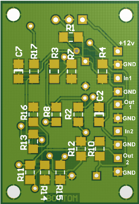
The full circuit and component overlay is available for download HERE.
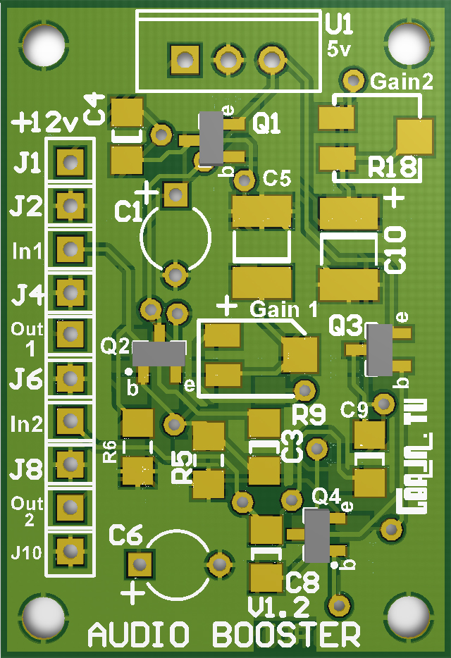
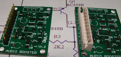
Several options for making connections to the pcb.
Hard-wiring is another.
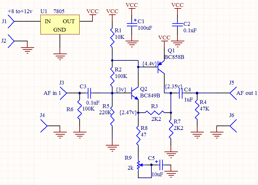
Two Channel Audio Booster
Using two discrete transistors per channel, this high gain, low noise audio amplifier is ideal for boosting line level audio signals that are in need of a lift. It is inexpensive and small so that it can be used in any number of situations where a VeroBoard might otherwise be used. Amplifying by over 12dB per channel, the output levels can be preset by a trimmer and will boost audio inputs up to 1 volt pk-pk by up to 5 times. The preset control adjusts the maximum gain but does not act as a full volume control. If total audio level control is required a pot should be added either before the input capacitor C3/C8 (10k log) or after the output capacitors C4/C9 (5k log)
Provision is made for an optional 5v regulator to be fitted allowing any DC supply from 8v to 14v to be used.
A full circuit diagram and the overlay pictures are downloadable HERE. A Bill of Materials is HERE.
The values of components shown in the circuits are intended for Amateur Radio use, particularly speech. To use for ATV or for music the output coupling capacitors C4 & C9 could be increased to 10uF
and C5 and C10 could be 22uF. Decoupling is split between the two sections giving a larger total decoupling value.
No crosstalk was detected between the channels. If either channel is not to be used the input pin for that channel should be grounded.The high gain first transistor has two feedback paths, R2 and R3 which also controls the dc bias and keeps the amplifier stable under various input/output loadings.By decoupling the feedback on Q2 emitter with C5 via R8 the gain of the stage can be controlled simply.R6 and R4 are not normally needed if the circuit is left installed in a stage. They are however, useful if there is any device to be plugged or applied to the input/output by external connections which might cause a dc 'plop' sound to be amplified.
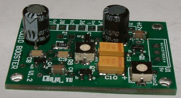
I suggest starting assembly on the bottom side as components on the top side are taller. Then on the top side, start by adding preset trimmers R9 & R18. Add the four transistors.Then all resistors and small value capacitors and the finally the electrolytics. If being used, fit the 5v regulator and fit the wires connector.
New to Surface Mount Devices? Here are some tips....
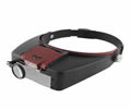
Fitting SMD components. You must have magnification and light. A magnifying headset is ideal, but a large bench magnifier is fine. Solder must be thin, eg 0.7mm (22swg). When fitting 3 legged devices such as transistors or presets, fit the single leg first then adjust the position of the other end so that the legs are aligned with the solder pads. 'Tombstoning' is a common problem with SMD resistors where one end lifts into the air whilst the other is being soldered. Keeping a gentle pressure on the centre of the component whilst soldering is best but can be tricky when you have only two hands! Practice can get the best results. Keep resistors and capacitors as straight as possible to avoid shorting the soldered end to nearby tracks.
FAULT-FINDING.
As you can see in the circuit diagram, there are voltage readings around the transistors. First check all resistor values are correct. If they are good, check with a magnifying glass the solder of components and ensure there are no solder splashes or tails especially between components and any nearby vias. (vias are the through-plated connection holes).Both channels should have the same voltage readings. If you do not have an oscilloscope and if no audio is coming through try bypassing each transistor with a 10uF capacitor to see where the audio is dissappearing.
UPDATES:
Will appear here..

 no menu? click here