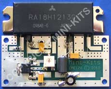
from Mike, G8LES
The module should be set to 4-5amps standing current*
The drive should be kept below 400mW to prevent damage to input FET.
Carefully prise the plastic cover off, after running a stanley knife along the glued edge.
The soldering can fail on the coupling chip capacitors between the first and second stage if the drive level is too high.
Pressing down hard on them with a plastic trim tool will prove it.
Most modules can give up to 40 watts continuous into a piece of RG412 directly off the output pin. (They do not like connecting to PCB track.)
Lots of earthing around the module..... every 2 cm PCB link- throughs or screws.
The module ceramic PCB normally cracks next to the output transistor and the 12 volt track goes open circuit.
Do not use a "magnastat" Weller soldering iron or one with a magnetic switch in the element as it will blow up the gates of the FETs.
Even an electronically controlled soldering iron must be earthed to the base plate.
Check the gate voltage is around 2 volts: if not, the device is damaged.
The spec sheet says when soldering the RA18H onto a board not to exceed 350'C for longer than 3 seconds.
If drawing no current , remove the drive and connect the DC supply. Follow the path from the DC pin (2nd from right in photo) it may be open circuit and supplying no volts to the first and second stages. A wire soldered along the track will attach to component ends ok.
Mike suggests soldering a 'blob' between the 390R and capacitor directly below the output transistor as this is the area that tends to crack on the substrate if the fixing screws are not mounted absolutely flat thereby putting a 'twisting' to the substrate which then cracks under hot conditions.
P.S. from DK: *There is some debate about the actual quiescent current setting. I suggest setting the quiescent current to about 2.5A per RA18H initially for digital ATV use . Increase it gradually towards 4A noting linearity or quality readings on digital tx. Drive to a single chip will only need to be 150mW depending on desired output level. Linearity drops off rapidly above 20W output per RA18H . The above notes can also apply to other Mitsu chips, Often the cause of cutting out when chip is hot.. well worth checking the dc feeds for continuity before binning any chip. Fitting small ferrite beads onto the legs can help reduce instability in the PA stage..
GETTING HIGH
There are a few mods worth doing if you are intending to use the RA18H
above 1300MHz. Power drops off rapidly above this frequency and the mods will raise the output for use up to 1318MHz. These have been suggested by Mike G8LES.

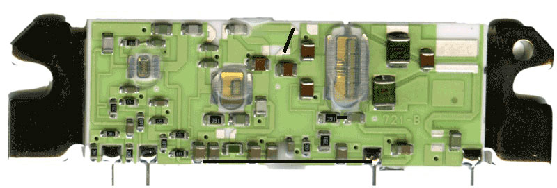
Place a short connecting wire as shown on the top of this picture effectively shortening the input line to the final FET. The other wires are described on the other Repair Notes window. Make small loop using the input pin wire,extreme left on this picture, it helps to improve the match to the input line.