![]()
KeepITCHeap!
A
beginners 23cm yagi
COMPONENTS LIST:
1 metre
(or more) of Westflex103
A
mug of coffee (Optional )
That's all !
This is not intended to replace a proper or commercially manufactured aluminium
yagi, but will get you local atv pictures quickly & very cheaply and
has an swr down to below 1.3:1 on 1255 Mhz
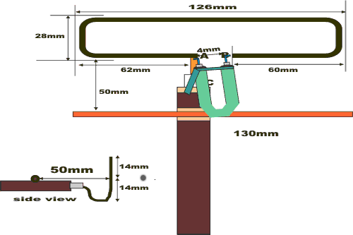
Cut
a length of cable to 130mm. This will be used for the matching balun which
should be 10.5cm long plus the 10mm at each end for connecting to the
dipole.
Using a stanley knife cut into the remaining cable down to (but not through)
the centre conductor at 500mm length. Draw off the outer, braid and sheath
and plastic spacer from the cut exposing the copper centre wire.Keep for
later use.
Trim back 10mm of outer black pvc fold back the braiding and bend the
wire as shown in pic1 to bring the centre of the folded dipole level with
the westflex cable in order to let the reflector and director wires align
with the middle of the dipole when viewed from the front.
PICTURE 3
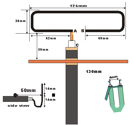
Slice 10mm of the balun wire outer sleeving , copper sheath and braiding off leaving the centre wire and its plastic spacer. Trim off the end 5mm of this inner sleeve so that the end 5mm of centre wire is exposed.Solder the two ends of the balun (A and B ) to the dipole and the braiding should be soldered as near as possible to the braid of the main cable(C). You may find that a piece of braiding taken from the off-cuts will wrap around the baluns' braiding and enable a good solder joint to be made.
It is not intended as a long term aerial , just as a cheap and quick way for the impoverished novice to get local atv pictures.Depending how far you are from the transmitter a small preamp would be advisable, ideally at the aerial end to help overcome losses and noise in the down cable.