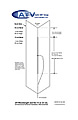
Slot design (click image to view pdf)
Much easier to make than cutting a slot into a circular pipe, this design uses a 1mm flat copper or brass plate with a slot in the centre with the plate bent to a 90°' corner. Complete with charts and measurements for 70cm, 23cm and 13cm.Click on the image to get the pdf download.The slot measurement is the actual size for cutting before bending.

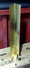
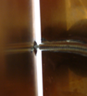
The connection to the centre of the slot.Not easy to photogr\aph, see the close-up below. If preferred a small bore e.g 8mm central heating pipe can be used to slide the cable through once soldered so heat will not damage the cable.
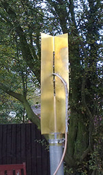
Aerial shown was made by G4KLB

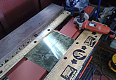
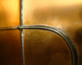
Another slot under construction and testing, this one made by Peter G8DKC.
Peter has used brass for the construction. As you can see he used a angle grinder to cut the slot.The lower part of the plate was cut and bent to fit the pole.

Designs for
2 meters and
23 cms
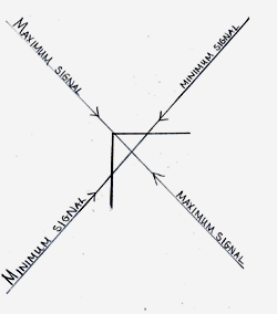
If a yagi is impractical at your location then a slot is a good alternative. It has much lower gain (about 5dBi) but receives/sends over 360 degrees thus does not need a rotator. Here is a fairly simple- to- make alternative to the Alford slot, maximum radiation is in front of, and behind, the slot with minimum radiation at 90° to the slot. See diagram on this page.
It is also wideband with a fairly flat response making it ideal for ATV. Most images on this page are of the 23cm version.
Slots can be made for use on 70cm, 23cm or 13cm, but accuracy becomes more important as the frequency increases.
Based on data supplied by
Dave Mann G8ADM
G8ADM
SLOT
ANTENNA
A close-up of the connection at the centre of the slot. The centre wire is soldered to the 'left' side in the picture while the sleeve is trimmed back and soldered to the 'right' side. (No left-hand wire, it is just a reflection in the copper). Colin cut the slot with a 'nibbler' tool..It would be wise to fold the centre wire after it passes through the plate and solder it that side too.
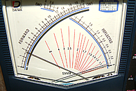
The SWR readings taken by me on the repeater output frequency of 1304. (about 1.25:1)
Gently bending the side wings together slightly gave a further improvement.
Dave G8ADM tells me: The aerial is tuned by adjusting the slot length whereas the width of the slot determines the impedance (50 ohms).The gain of my slot is a little over 6dBi.
The polar diagram is nominally an omni.
Compared to an Alford Slot the internal losses are very much lower so all the power is radiated from the antenna.
The aerial requires a cover with an internal diameter of at least 3 3/4" or 92mm so a 4" tube would be fine.