
Look here for a polar plot of 2 X double-double quad, half of that shown diagrammatically above (Polar plots and antenna data made with K6STI AO software).
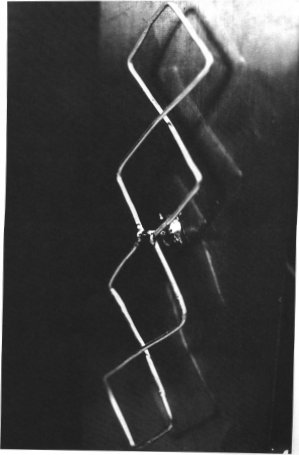
Below is a picture of the actual test antenna showing the arrangement of the wire forming the quad loops. The reflector in this case is a piece of aluminium sheet, where the antenna I use has 1 cm square wire mesh as the reflector. This reduces the wind loading and weight of the array. It measures 1 metre high and 50 cm wide. Each side of the quad loop is 6 cm long and made from a wire gauge which is self-supporting. I am using 2 mm enamelled copper wire.
The original article in the ' UHF Compendium ' claims the gain of the single double quad antenna with plane reflector to be 11 dB (no ref. is shown in the figures), with a comparable gain to a 10 element Yagi. This is the polar plot I managed to achieve with a double quad arrangement as shown below.

Stacking Antennas by G4CYA
DX on VHF is usually worked with horizontally polarized beams, so the following description is based on this model.
It is quite common to combine more than one antenna to achieve more directional gain in an array. Usually antennas are grouped in even multiples i.e. from one antenna 2,4,8 etc. although it is possible to have odd numbers like three or some times six, but this gives added complications of matching and feeding.
Generally stacking refers to placing one antenna vertically above another; baying usually refers to having the antennas spaced horizontally apart (side by side) and of course a combination of these as in a box of four.
The gain achieved by doubling the array is usually just less than 3dB (2.6-2.8 dB) at optimum separation. You might ask what is optimum separation. Well this is the minimum distance the antennas must be separated so that their capture areas are not overlapping, shown diagrammatically below.

The capture area of an antenna is it's ability to collect or intercept incoming energy from free space and is related to gain. i.e. A=Gi/4p
A is the capture area (in square wavelengths),
Gi is the gain over isotropic (as a ratio).
So a dipole with gain of 2.15 dB over isotropic has an effective capture area of 0.13 square wavelengths.
A Yagi of 10dBi (a factor of 10) has a capture area of about 0.8 square wavelengths.

It has been shown that optimum spacing of Yagi antennas is a function of the half-power beamwidth (Q) in the stacking plane. Dopt=l /(2sin(Q /2))
Dopt is the spacing in l, at which the stacking gain is maximum, and (Q) is in degrees.
The beamwidths in the E and H plane are very often different so the stacking and baying spacing will be different for optimum gain. It must be remembered that there are other losses to take into consideration such as the power splitters and feeders.
Stacking antennas too far apart can increase the sidelobes of the array. It is therefore better to have slightly closerstacking without too much noticeable loss in overall gain.
For a short Yagi of say 5 elements it may have a beamwidth of 50 Degrees in the E-plane and say 70 Degrees in the H-plane. It would have a horizontal separation of 1.18l and a vertical separation of 0.87l centre to centre.
Stacking antennas reduces the beamwidth of the array in the vertical or H-plane by approximately half. Baying reduces the horizontal E-plane beamwidth by approx. half. So in the case of the 5 element Yagi, the 5X5 array stacked would be 50 degrees in the E-plane, and 35 degrees in the H-plane. If the array was bayed the E-plane would be reduced and the H-plane would remain the same.
Depending on what you are wanting to use the array for, the beamwidth can be adjusted by selecting a stacked or bayed arrangement. For normal troposheric scatter operation a stacked arrangement is preferable. This would yield a wider horizontal beamwidth while reducing the vertical beamwidth, thus reducing the power that is wasted radiating up into space or heating up the ground in front of the array.
Having an interest in VHF National Field Day, I made a transverter for 23 cm. This works very well but at some sites there is a fair amount of commercial interference, plus the use of multi- bands on Field days. I decided to look at a bandpass filter I could make which would give both low insertion loss with good out of band rejection, and could be in line on transmit or receive.
The design I have used is not original. I thought it would be as well to use a tried and tested arrangement as I have limited test equipment to set up this filter at 23 cm. Ideally a network or spectrum analyser would be very useful, but my bank account will not stretch to such a piece of kit at this time.


Above: The interdigital filter constructed with aluminium
The construction method I have used is in aluminium bar and plate. Fig.2 should help with the description.
The main frame is constructed using 1 inch X 1/4 inch (25 mm X 6 mm) aluminium bar. To this rectangular frame, the two side panels which are made with 2.75 inch X 1/8 inch (70 mm X 3 mm) aluminium, and are attached with M3 set screws into holes drilled and tapped along the top and bottom edges of the frame.
Note the number of screws on each side, 16 in each side panel, to make sure of a good electrical shield at this high RF frequency, and to improve stability.
The input / output connections are made with flange mount ' N type ' connectors, which just fit the 1 inch size of the frame. They are also attached with M3 set screws into threaded holes.The resonant elements are made with 1/4 inch (6 mm) aluminium rods 50 mm in length, tapped and bolted to the frame. The adjusting screws are M5 bolts with a lock nut to tighten up when the resonant frequency is found.
The coupling loops on the ends, are short lengths of 1.5 mm diameter silver plated copper wire, soldered to tags under the first and last inductive elements, and soldered to the centres of the ' N ' connectors.
.jpg)
Fig.2. Inside the Band-pass filter
As you can see from the inside view of the filter it has five tuned circuits. It has low insertion loss, less than 1 dB; and a has been designed as a broad band filter for transmitters, but it does have good rejection with low ripple throughout the 23 cm band.

Fig.3. The frequency response of the filter tuned for 23 cm
The above shot of the frequency response of the filter shown with a vertical scale 10 dB/cm. The horizontal scale is 50 MHz/cm. The attenuation at 1268 MHz is greater than 40 dB.

Shown above is the normal arrangement for a two way power splitter. The end that has the two 'N' sockets is where the two antennas are connected with equal lengths of 50 Ohm coax, the other port goes to the TX/RX, again in 50 Ohm coax. Low loss coax in all the cables is important for the best results. The better method for matching more than one antenna is to use a power splitter/combiner and making your own section ofl/4 line.
I make mine with 1 inch (25.4 mm) square section tube; it has 2 mm wall thickness, and a round centre conductor, using the formula: Z0 =138log10{1.08*D/d}
Z0 = impedance l/4 line
Where D = inside dimension of outer conductor and d = outside diameter of inner conductor
Knowing the value for the 1/4 wave-line for two antennas is 35.35 Ohm and the dimension D, it is easy to calculate the dimension of the inner conductor, then choosing a size of tube closest to the preferred value. I have found that 12.7 mm or 1/2 inch tube works OK for the inner conductor.
The outer can be copper, brass or aluminium. The inner has to be soldered so copper or brass is used here. It is useful to choose 1 inch square section for the outer because this allows the use of square flange mount N type sockets. The inner has to be a 1/4 wave long and this is in free air so for 2 metres this will be 52 cm. The outer has to be longer to allow for the flange mount sockets and to put waterproof caps at each end of the tube.
Extending this information for power splitters for four antennas. The same principals are involved, now we are looking to match four, 50 Ohm load impeadances combined to give 12.5 Ohms. Using the formula for l/4 line transformer, it is calculated to be 25 Ohms. Using the same outer dimensions as the 2 way splitter would require an inner tube of 14.94 mm or 15 mm. All four antenna ports are connected at one end of the power splitter.

You must remember that each antenna must have exactly the same length of low-loss coax between its feed point and the power splitter. Otherwise the phase relationship of the array will not be maintained and cancellation of signal will result.
It is also possible to make a half wave line fed at the centre, thus forming two l/4 transformers. With this arrangement two loads are connected at one end and the other two loads at the other as shown in the diagram below. This may be more convenient if you are building a large array and need to balance out the positions of the feeders.
For this splitter each pair of antennas combine to give 25 Ohms, and use a 50 Ohm quarter-wave transformer to give 100 Ohms; when the two 100 Ohm points are connected in parallel at the centre, the result is 50 Ohms.

If you make a splitter like the one shown here you will have to drill a large enough hole on one of the sides at the centre so that you can solder the centre connector to the conductor. Then a ' blind grommet ' can be used to weather proof. I usually give the whole thing a couple of coats of yacht varnish, but don't paint the threads of the ' N types '.
Here is a table of values for two way and four way power splitters using a single l/4 line.
The word balun means (Balanced to Un-balanced) transformer. And of course coaxial cable, which is the most common feeder, is unbalanced electrically. Connecting coax directly to an antenna could mean that some current will flow in the opposite direction on the outer or braid of the feeder. A correctly designed balun can prevent this and any of the problems that can arise when RF flows on the outer of the coax. The balun can also help preserve the best radiation pattern for the antenna.
Obviously some antennas can be fed directly with coaxial cable e.g. antennas that do not have a balanced feed point, such as a gamma matched Yagi.
At VHF baluns are used both as impedance transformers, as in the case of a 4:1 balun to feed a folded dipole which would have an impedance of 200 Ohms, this would give a good match into 50 Ohm coax. The construction of such a balun is straight forward, but must be made such that it is low loss.
1:1 baluns come in several forms. At VHF it is easy to make a sleeve balun or a Pawsey Stub which is a shield surrounding the final l/4 of coax at the antenna feed point.
MEASURING ANTENNA PERFORMANCE by G4CYA
When I make a new antenna it is nice to find out how it performs. The usual method I use is to set up the test antenna and a dipole. At some distance away (I usually measure over a distance of 1/2 to 3/4 of a mile) I get a colleague to set up a low power signal. Over a clear line of site path with no nearby obstacles. The low power beacon provides a reliable reference point to carry out the measurements. At the test side I have a receiver connected via an accurate stepped attenuator to either the test antenna or the reference dipole. First I set up the receiver with the dipole connected, and I adjust the S meter, with the aid of the attenuator, to a SET point (a rig with a large analogue meter is useful here), to which I can be sure I can re set to, say S9. Then I replace the dipole with the antenna under test, and assuming all is well and the antenna has some gain over the dipole, readjust the S meter reading with the attenuator till it achieves the SET point. Then it's just a case of reading off the difference on the attenuator to give the gain of the antenna in this situation.
That gives the gain of the antenna over the ref. dipole. Now a similar method can be used to give FB and overall polar pattern if you want to take a few more readings. This relies on calibrating the 'S meter' with the stepped attenuator, and again using the distant signal source to take readings.So far with this method I have achieved good correlation with computed data and also with published figures for known antennas.
Lastly testing on air over a much greater distance, although this can be difficult especially if there is QSB to contend with. When I first used the 2X2-element array I found that it was giving extremely good results considering the size of the antenna. Tests over a path of 300 miles with GU3EJL, on the Island of Alderney in the channel Isles, showed considerable improvement over a single 2-element beam although results just relying on S meter readings.
I have also tried a single 4-element beam in comparison with the 2 over 2 stacked and again the results seemed to come out on the side of the 2X2-element.

