
AUDIO LIMITER/COMPRESSOR
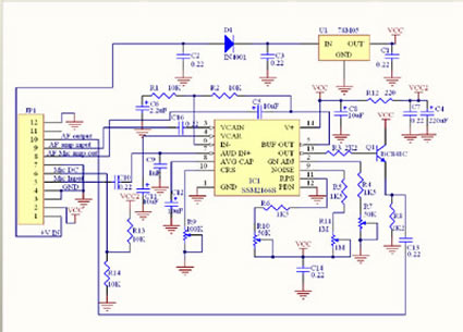
Please click circuit to get latest version PDF .
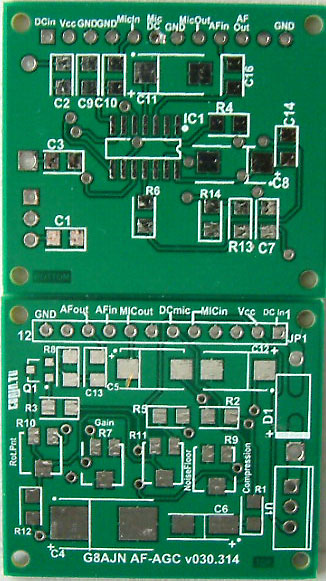
Microphone AVC/Compressor with 60dB range & adjustable noise floor.
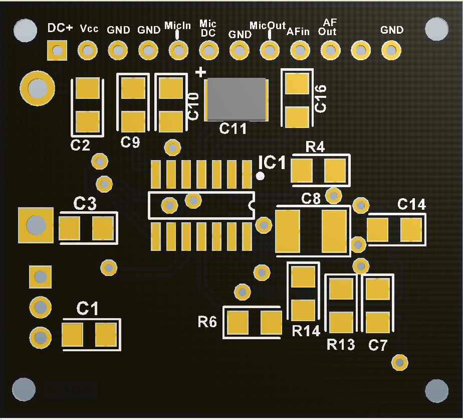
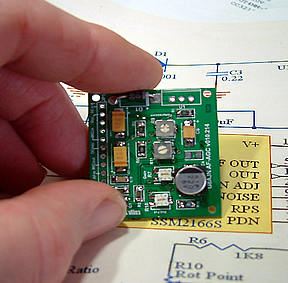
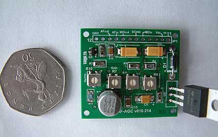
Designed to give >1v 1k audio level for Comtech or Digital encoders from standard or electret microphone. Double sided board size: 40mm x 35mm (approx 1.5" x 1.75").
DC input is 8v-12v .

Contact me at

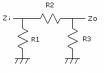
'T' Attenuator
values for
audio use
(75 ohms)
values for
audio use
(75 ohms)
NOTES: Only C16 & C13 need to be 0.22uF.
The others C1,C2,C3,C7 are just decoupling and 0.1uF appear to work ok. Alternatively it is possible to piggy back two 0.1uF to save money. C8 can be any value up to 100uF. C4: 100uF will be OK. D1 can be smd, remove the coating over the tracking to fit. If not using another input on JP1 pin 9 then simply link together JP1 pins 9 and 10 and s/c C16. Presets can be 3mm format if 4mm are not available. Some capacitor physical size descriptions in the original parts list were not correct. C4,C5,C11,C12 are larger than 1206, and can be aluminium SMD if preferred.
Not working? Here are the readings you can expect on IC1. Set preset pots to midway. Some readings may depend on the pot settings so use this as a general guide. Most problems encountered have been due to solder bridges particularly on IC pins.


| R1,R3 / R2 | Preferred | Values | |
| 75ohm | Actual | E12 | E24 |
| 1dB | 1304 / 8.6 | 1200 / 8.2 | 1300 / 9.1 |
| 2dB | 654 / 17.4 | 680 / 18 | 680 / 18 |
| 3dB | 438 / 26.4 | 470 / 27 | 430 / 27 |
| 4dB | 331.4 / 35.7 | 330 / 33 | 330 / 36 |
| 5dB | 267 / 45.5 | 270 / 47 | 270 / 47 |
| 6dB | 225 / 56 | 220 / 56 | 220 / 56 |
| 8dB | 174.2 / 79.2 | 180 / 82 | 180 / 82 |
| 10dB | 144.3 / 106.2 | 150 / 100 | 150 / 110 |
| 12dB | 125.3 / 139.8 | 120 / 150 | 130 / 130 |
| 18dB | 96.6 / 29.3 | 100 / 270 | 100 / 300 |
| 20dB | 91.6 / 371 | 100 / 390 | 91 / 360 |