Andrew Alford
Born Russia Aug 5 1904 - Died Jan 25 1992
Alford seems not to have designed the slot antenna as we use it
now, but he did realise an omni antenna using an array of circular loop
antennas and it was obvious from there that by closing the gaps and increasing
the number of loops one would in effect have a tube with a slot in it.
The slot antenna was invented in 1938 by
Alan Blumlein while working for EMI. He invented it in order to produce a practical type of antenna for VHF tv broadcasting that would have horizontal polarization, an omni-directional horizontal radiation pattern and a narrow vertical pattern.
THEORY
Links to useful sites.
w1ghz
ALFORD SLOT ANTENNA
click the pictures to link

Designs for
2 meters and
23 cms
If a yagi is impractical at your location then an Alford slot is a good alternative. It has much lower gain (about 5dBd) but receives over 360 degrees thus does not need a rotator.
Slots can be made for use on 70cm, 23cm or 13cm, but accuracy becomes very important above 23cms.
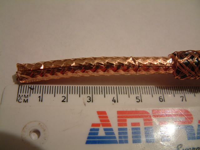
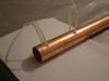
I decided to use Westflex 103 cable without a connector at the slot antenna to reduce losses and because all the problems that I had over the years had come from faulty connectors. An N socket could be fitted if preferred and does help reduce any pulling from the weight of cable. The pipe was 35mm x 900mm. Can be 600mm upwards.The length of the tube beyond the slot is not important, in fact other aerials can be attached to the pole away from the slot. The Westflex 103 is too large for 15mm pipes where Quickform 141 or other semi-rigid etc is more suitable.
Due to the hard copper of the pipe I used there appeared to be no bowing at the centre of the slot, but cable ties would be useful if soft copper is found to 'bow' at the centre..
Weatherproofing: PVC pipe is likely to worsen SWR & needs to be >3 times the diam of the pipe and as thin as possible. I used black DPC sheet and PVC tape instead. They worked really well. I have tried EcoFlex 10 instead of Westflex. The flexability of the Ecoflex comes partly from its thinner sheath. This makes cutting slits a little more tricky than the firmer Westflex and means that care is needed as the cable is bent before connecting to the solder tags. Otherwise it seems a good alternative.
If you do make one of these slot antenna please let me know how you get on and I will pass on the info here for others to read. If you wish to keep the visibility of your antennas to a minimum I recommend that you consider making the
Bassoon.

My attempt at making a 23cm ALFORD SLOT Antenna-without a router!
TUBULAR (ALFORD) JVL SLOT ANTENNA By M. Walters G3JVL.
| Tube Dimensions(23cms) |
Slot Width |
Slot Length |
| 31.8mm OD, 20swg wall |
4 mm |
510 mm |
| 35 mm OD, l.lmm wall |
8 mm |
510 mm |
| 38.1mm OD, l6swg wall |
11 mm |
510 mm |
13cm version:
15 mm cent'l heat copper pipe
|
1.6mm |
260mm |
The slot antenna, which has been developed for 1.3GHz by G3JVL, is an easy means of obtaining an omni- directional radiation pattern with horizontal polarization . The antenna has a gain which depends principally upon its length and is typically 5 to 9 dBi . This is a better performance than other simple omni-directional antennae commonly used such as halos or whips. It is particularly suitable for a beacon or repeater antenna where an omni pattern is required with as high a gain as possible. In this application it is possible to stack two such antennae end to enc3 (as used at the beacon GB3IOW) and nearly double the gain. with higher path losses on 23cm compared to 2m and 70cm the extra gain makes it particularly useful as a mobile antenna. Spacing should be 1.5mtr feedpoint to feedpoint.
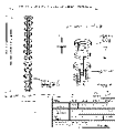
DESCRIPTION The antenna consists of a length of slotted tubing as shown in figure l. The width and length of the slot, the wall thickness and the diameter of tubing are all related and much experimental work has been done by G3JVL and G3YGF to evolve some working designs, details of which are given below.
SUMMARY The antenna represents a very practical means of realizing horizontal polarization with an omni-directional pattern and high gain on 1.3GHz. The bandwidth is sufficient to cover all of the band so that it would be suitable for any modes including TV. The circularity is very good (ratio of max to min gain) being typically ldB. This type of antenna has also been used on other bands successfully - G3JVL has used it on 2m, 70cm and 13cm. For further details contact Mike Walters G3JVL, or Julian Gannaway G3YGF', or the RSGB Microwave Committee. DK COMMENT:My experience is that aluminium slots seem to perform less well than copper or brass.
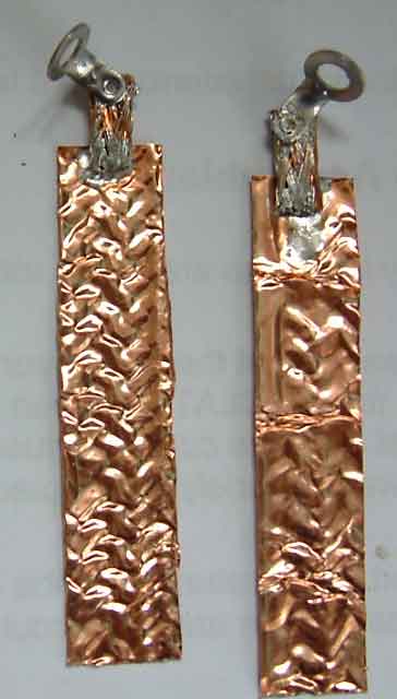
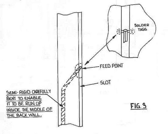
It is not necessary to connect the cable to the inside of the tube as it passes out of the bottom. However, a convenient method of mounting is to fit a shorting plate of some description across the bottom with an N-type plug or socket in it. The antenna can be mounted entirely by the N-type connector . This method is particularly convenient for mobile use where the N-type can be screwed on to a female back to back bulkhead fixed to the roof. The feed impedance of these antennae is approximately 200 ohms. A convenient method of feeding from 50 ohm coax is to use a 4:1 balun which is fabricated from semi-rigid coax. It consists of a piece of 0.141 inch (3.6mm) semi-rigid with two slots cut along opposite sides of the outer. The two leaves formed by the coax outer form a twin wire transmission line which is a quarter wave long, and short circuited at one end. This quarter wave resonator is excited by connecting the coax inner conductor to the end of one of the leaves. The two sides of the semi-rigid a and b are connected to the feed point of the slot . A convenient method of doing this is to attach small solder tags to the cable so that small screws can then be used to attach the balun assembly to the sides of the slot. The cable should be bent round after leaving the feed point so that it sits somewhere between the back wall and the center as it passes down the tube. The exact arrangement is uncritical so long as the cable does not come too close to the slot and upset its operation (apart from the feed point of course). The dimensions are, to a certain extent, interdependent. The velocity factor will be increased by decreasing the tube diameter, or by increasing the slot width. The wall thickness also has an effect since it determines the capacitance across the slot so that a thinner walled material will also increase the velocity factor. Thus, if a slightly smaller diameter tube was chosen than one of the designs, then this could be compensated for by using a slightly narrower slot so that the same velocity factor is achieved. Alternatively, the length of the slot could be decreased. The antenna would then operate with a lower velocity factor, but this would give a lower gain. For l.3GHz antenna, the tube diameter should be within the range of those given, any tube much beyond hese limits will not operate correctly. It is important that the operation is checked, particularly if any of the original design parameters are changed. This may be done by feeding the antenna with a signal at various frequencies and looking at the voltage distribution using a power meter, detector or analyzer with a small probe to pick up the radiated signal. The probe should be held close to the tube, but not directly in front of the slot (hold it 20 or 30 degrees round from the edge) and moved along its length. The diode current meter described in the microwave newsletter (08/81) would be suitable for this purpose. The balun works by taking the voltage on the unbalanced 50 ohm line and producing two output voltages relative to earth (the cable outer) which are equal to the input voltage but are 180 degrees out of phase with each other. The balanced load is connected between these two outputs and sees the difference between them, which is twice the 50 ohm voltage. Hence there is a 4:1 step up in impedance. The balun has a comparable bandwidth to the slot, about 10 to 15%. Note that the length of the cuts in the semi-rigid must be an electrical quarter wave long . Since the space between them inside is PTFE and the space around them outside is air, this gives an effective velocity factor of about 0.36. Thus the length is 0.86 times the free space quarter wavelength. If there is a significant gap between the leaves and the PTFE , then the velocity factor will be slightly higher.

IF covering the bottom of the tube always leave a drain hole for moisture to escape away from the N socket.
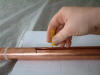
 Using PVC tape to mark the slot to be cut.( 35mm pipe is best : easier to work with)